Acquire mode is the workspace for live interaction with the Vimotis system. Use this mode when hardware is connected and you are preparing, monitoring, or recording an acquisition session.
Acquire mode supports:
- connecting or reconnecting to the data-acquisition hardware,
- reviewing acquisition, processing, and calibration settings,
- viewing live tensiometer, analog-input, and accelerometer plots,
- selecting the save folder and run file name, and
- recording data to disk.
Menus and Dialogs
When Acquire mode is active, these uniqe acquire mode menu actions are available:
- File > Reconnect: attempt to reconnect to the Vimotis POD.
- Edit > Calibration: open the Calibration window.
Toolbar and Run Controls

The Acquire toolbar includes the core session controls:
- Start or pause tap control,
- Save-path selection,
- Editable save folder field,
- File-name field,
- Collection duration field in seconds,
- Start or stop collection control, and
- Arm/disarm trigger with selectable rising-edge () or falling-edge () behavior. The input trigger high is nominally 5V, and the trigger level occurs between the high and low states as indicated in the product manual.
File names do not auto-increment by default. If the working directory contains a file of the same name, the existing file will be overwritten. This will be indicated by the filename in the box turning red before acquisition.
Channel Select
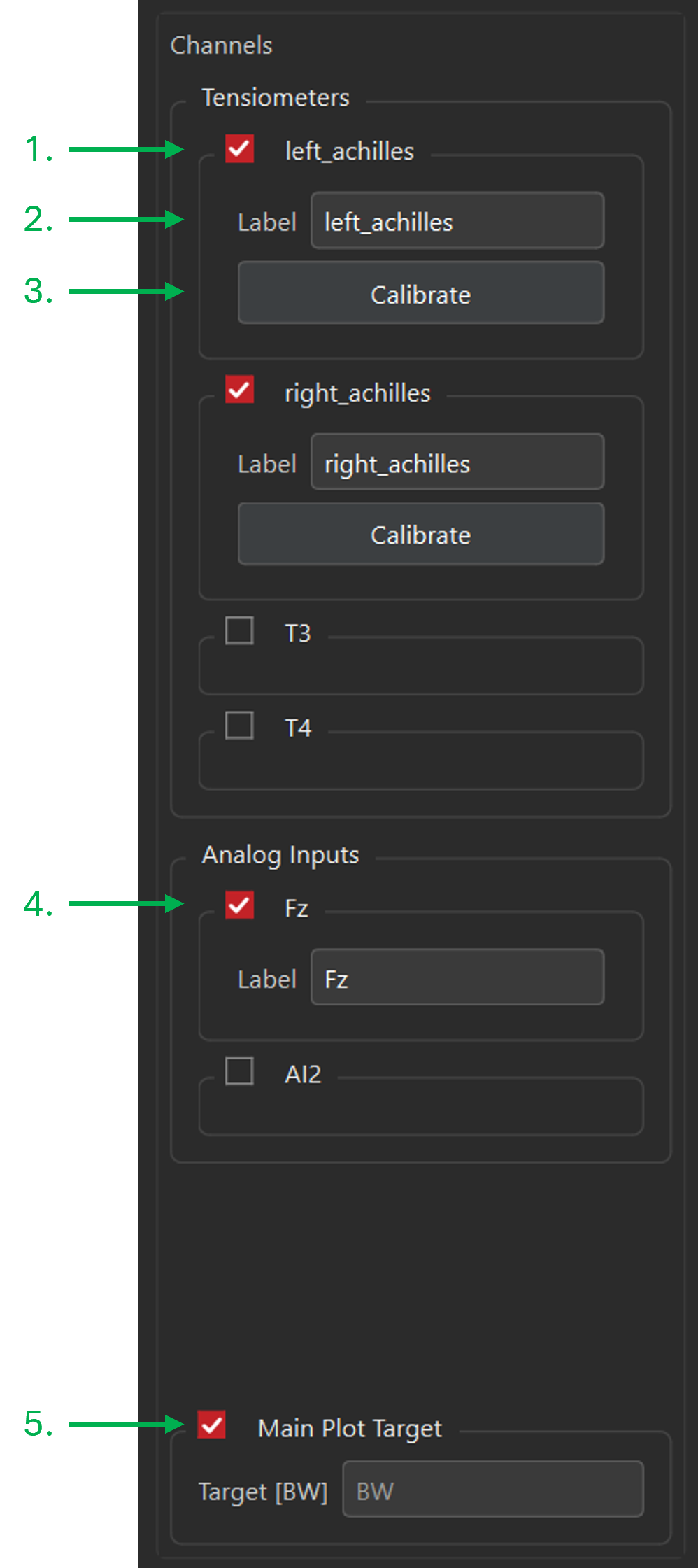
The left-side channel control area is used to choose which channels are visible and which signal is shown in the main plot target. Only active tensiometer and analog channels should be checked.
- The check boxes by each channel (tensiometer and analog) are used to enable/disable that channel.
- Each channel may be individually labeled to indicate the tendon or signal being measured. If no label is set, the defaults are T1-T4, and AI1-AI2
- The
Calibratebutton launches the calibration dialog (see Calibration Dialog) - The system has two analog inputs (±10V) which are sampled at 50kS/s synchronously with the tensiometers. To match sample rate between tensiometers and AI channels, decimate the AI channels by 5k.
- An optional threshold marker may be enabled as a visual reference or for biofeedback. This draws a horizontal line on the wave speed / load plot at the specified y-axis location.
Plots and Plot Interactions
Acquire mode provides multiple live plot areas:
- Tensiometers: main wave-speed or calibrated-load display,
- Analog Channels: analog input plots,
- Accelerometers: per-sensor accelerometer views.
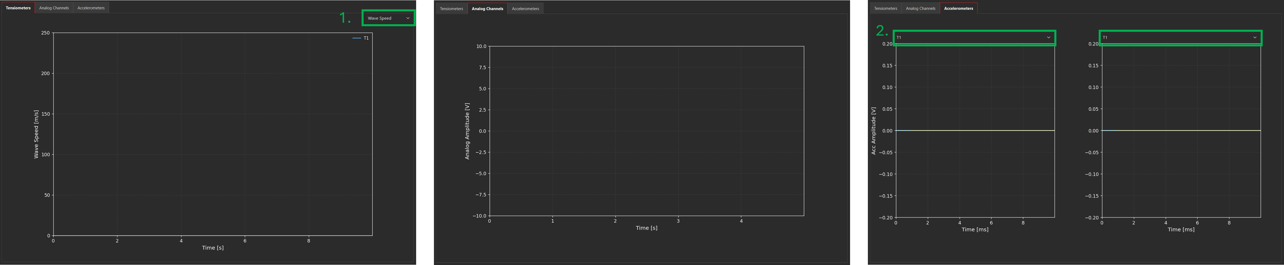
- Switch between plotting wave speed and calibrated load data using this dropdown.
- Select an active tensiometer channel from one of these dropdowns to view its raw signals.
Plot Interactions
- Plot items can be hidden/revealed by clicking on the legend entry to toggle visibility.
- The x- and y-axis zoom is controlled by clicking and dragging in the direction and over the region of interest. Double-click to reset the axes.
Calibration
For best results, Vimotis tensiometers should be calibrated each time a sensor is placed on a participant. The calibration should be performed in the posture and over the load range of interest. Slight variations in anatomy, sensor position, and strap tightness may cause variations in the absolute wave speeds measured, and thus the relationship between wave speed and tendon loading. Approximate parameters describing this relationship are used at software launch, giving uncalibrated load estimations.
The calibration protocol compares tendon tensiometry data with external measurements, such as dynamometer or force-plate data, to relate the recorded signal to known tendon loads. By default, the software assumes that the net moment at the selected joint is produced entirely by the tendon being measured (adjust in Advanced Settings). Tendon load is calculated using the joint moment and the tendon moment arm at that joint. A tendon moment arm value must be entered for each calibration.
Calibration Summary
The Calibration workspace is used to review or update per-tensiometer calibration settings. Edit > Calibration opens the calibration summary page with all active channels displayed.
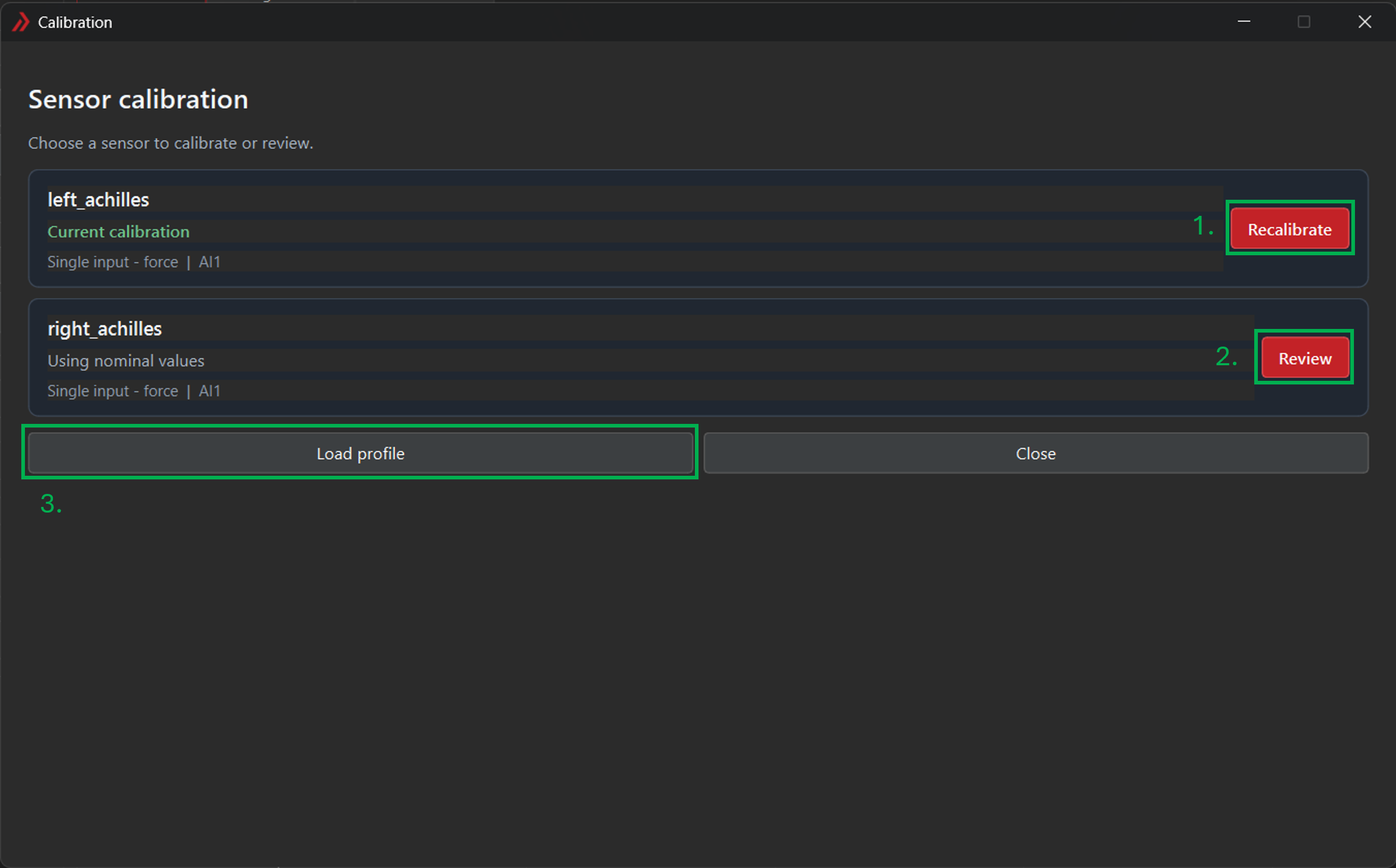
- Review and edit a calibration applied to an active sensor.
- Begin a new calibration for an active sensor.
- Load a saved calibration archive. It is recommended that the current active channel configuration match the active channels in the calibration archive.
Calibration Workspace
The calibration workspace is used to manage calibration instrument settings, collect calibration data, and compute calibration fits.
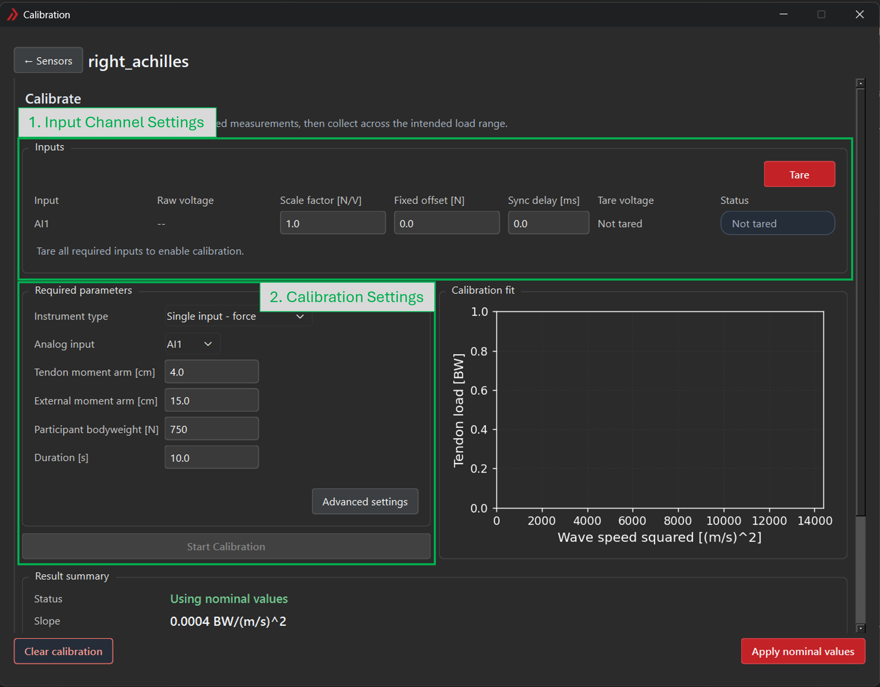
Input Channel Settings contains the parameters required to convert the voltage signal(s) received from calibration instruments (e.g. force plate, dynamometer) to relevant force/torque/position values.
Setting Description Scale Factor Scale factor for the connected instrument. Units depend on the type of instrument. Note that the sign of the scale factor may need to be changed to give positive calibration values (e.g. flexion vs. extension) Fixed Offset Some instruments may have a known fixed voltage offset for a "zero" reading, though most often this will be zero. Sync Delay [ms] Known delay from physical dynamic input to the calibration instrument and analog voltage output. Failure to account for this delay may present as hysteresis in the calibration data, since measured wave speed and instrument output will be out of phase by the sync delay. NOTE: observed hysteresis may also result from physical sources like friction in the calibration apparatus, so confirm that the sync delay is truly nonzero before applying. Tare "Zero" any bodyweight or other voltage offsets. Tare is required before a calibration can be collected.
Calibration Settings contains calibration-specific parameters.
Setting Description Instrument Type Switches between Single-input - forcecalibration andSingle-input - torquecalibrations.Single-input - force: assumes a force-based instrument (e.g. load cell, force plate) with a fixed external moment arm.
Single-input - torque: assumes a torque-based instrument (e.g. joint dynamometer); external moment arms are not required.Analog Input Choose which analog input ( AI1orAI2) is connected to the calibration instrument.Tendon moment arm [cm] Approximate moment arm of the measured tendon, assumed fixed tendon moment arm. External moment arm [cm] Only available for Single-input - forceinstrument types. Moment arm of the applied calibration force about the joint of interest.Participant Bodyweight [N] Weight of the participant in N. The default value is determined by the value saved in Preferences. When a calibration is active, the value in this field takes priority over the Preferences setting. Duration [s] Duration of the calibration collection. Once the instrumentation has been tared, the
Start Calibrationbutton will become active. During the calibration task, the live data will populate the graph axes.The calibration will fail if too few valid calibration points are recorded or the calibration fit is below the required threshold. Parameters pertaining to the fit and acceptance can be configured via the
Advanced Settingsdialog.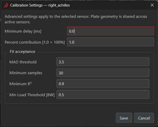
Figure 6: Advanced calibration settings. Setting Description Minimum Delay Minimum delay offset correction. Percent Contribution Percent contribution to the total physiological joint torque by the muscle-tendon group for the selected tensiometer. Fit Acceptance MAD Threshold Outlier criteria: Mean Absolute Deviation. Used to determine whether data points should be included or excluded from the calibration fit. Minimum Samples Minimum number of data points, after exclusions, for a successful calibration. Minimum R2 Minimum fit correlation strength for a successful calibration. Min Load Threshold [BW] Minimum load threshold below which to exclude data from the calibration fit. Used to eliminate the effect of uncertain low-load measurements from the calibration.
Data Display - Once calibration is complete and meets the specified parameters, the calibration will auto-compute and the calibrated data will be displayed.
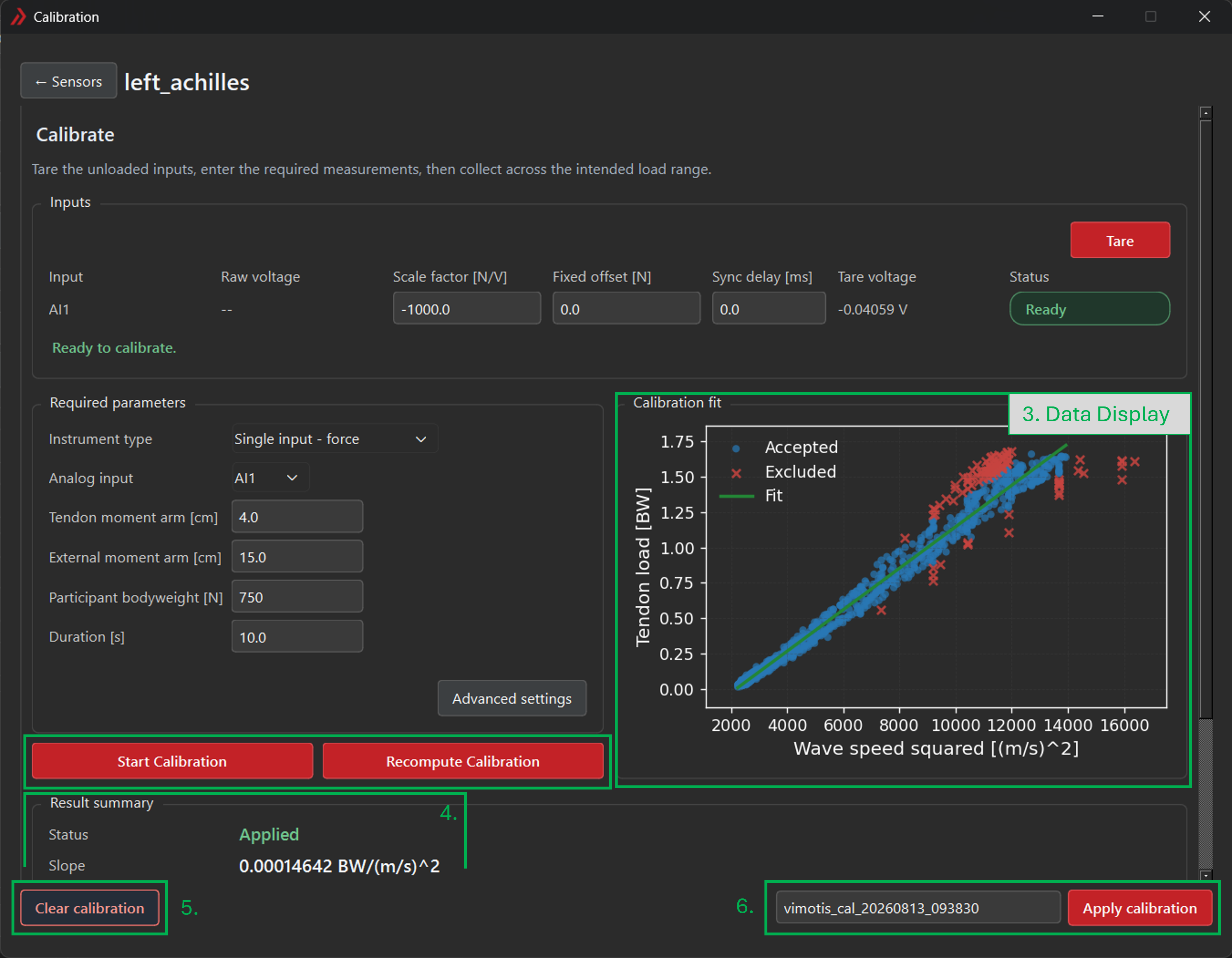
Figure 7: Calibration workspace, after a calibration has been collected. Modifying parameters after a calibration has been taken will require the calibration to be recomputed using the
Recompute Calibrationbutton. Alternatively, the calibration can be taken fresh with theStart Calibrationbutton.
Results Summary details the results of the calibration fit.
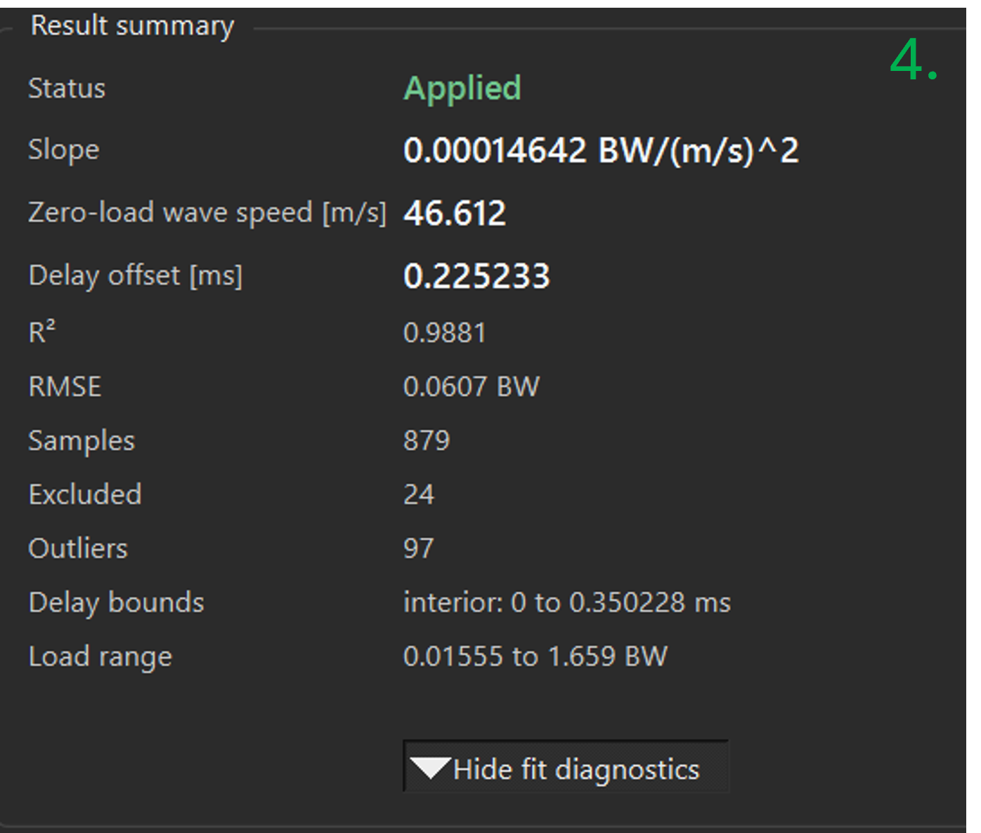
Figure 8: Calibration results summary. - Status: Shows whether the calibration is current, ready to apply, using nominal values, or requires recomputation or new data collection.
- Slope: Describes the relationship between tendon load and squared wave speed. It is used to convert measured wave speed into estimated tendon load.
- Zero-load wave speed: The wave speed predicted by the calibration model when tendon load is zero.
- Delay offset [ms]: A fixed timing correction applied to the measured wave travel time to compensate for delays in the measurement system.
- R2: Indicates how closely the calibration model fits the collected data. Values closer to 1 indicate a better fit.
- RMSE: The typical difference between the reference tendon loads and the loads predicted by the calibration model.
- Samples: The number of valid data samples used to calculate the final calibration.
- Excluded: The number of samples omitted because they were invalid, nonpositive, below the load threshold, or outside the acceptable timing criteria.
- Outliers: The number of otherwise valid samples removed because they differed substantially from the overall calibration trend.
- Delay bounds: The permitted range within which the delay offset was determined.
- Load range: The lowest and highest reference tendon loads included in the final calibration fit.
- Clear Calibration and reset to the nominal calibration values.
- Apply Calibration becomes active once a valid calibration has been collected and computed. If changes are made to fit-relevant fields, recompute the calibration before applying. When the calibration is applied, the data is stored in a standalone archive. To prevent accumulation of unnecessary calibration files, the file is overwritten by default, but multiple calibration files may be saved by changing the file name. The filename will display as red in the box if a calibration archive will be overwritten.
Status Messages
The status area reports operating state, connection messages, recording status, and errors, and is located in the bottom left corner of the application.
Normal Output
The current implementation writes acquisition output to an HDF5 file with an .h5 extension. All data captured live as well as post-processed data are contained within this .h5 file.